
















A long distance transceiver is an optical module designed to transmit Ethernet or data center traffic over extended single-mode fiber (SMF) links, typically ranging from 10 km to 120 km without intermediate regeneration. Unlike short-reach optics that operate over multimode fiber at 850 nm, long distance transceivers primarily use 1310 nm or 1550 nm wavelengths to minimize attenuation and support stable signal propagation across metro, inter-campus, and carrier networks.
In modern optical systems, distance capability is not determined by wavelength alone. Reach depends on a combination of transmitted optical power (Tx), receiver sensitivity (Rx), total link attenuation (dB/km × distance), connector and splice loss, and chromatic dispersion. For example, standard single-mode fiber (ITU-T G.652.D) exhibits typical attenuation of approximately 0.35 dB/km at 1310 nm and around 0.20–0.25 dB/km at 1550 nm. This lower attenuation window is one reason 1550 nm optics dominate links beyond 40 km, particularly when paired with optical amplification technologies such as erbium-doped fiber amplifiers (Los EDFA).
Industry specifications define long-reach Ethernet optics under standards such as IEEE 802.3ae (10GBASE-ER at 40 km) and IEEE 802.3ba (including extended-reach variants). These standards formalize power budgets, wavelength windows, and dispersion limits to ensure interoperability across compliant equipment.
From an engineering perspective, long distance transceivers are commonly categorized by reach class:
LR (Alcance largo) — typically up to 10 km
ER (Alcance Extendido) — typically up to 40 km
ZR — typically up to 80 km or beyond (often vendor-specific or DWDM-based)
Each class corresponds to specific optical budgets and dispersion tolerances. As link distances increase, chromatic dispersion and accumulated attenuation become the dominant limiting factors, not simply output power.
Understanding how wavelength selection (1310 nm vs. 1550 nm), optical budget calculation, dispersion characteristics, and network architecture interact is essential for choosing the correct module. Selecting an inappropriate reach class can result in insufficient margin, receiver overload, or unnecessary cost escalation.
This guide provides a technically accurate and standards-aligned explanation of long distance transceivers, including reach classifications, wavelength considerations, optical link budget calculation, dispersion impact, DWDM integration, and deployment best practices. The objective is to equip network engineers and system designers with the criteria required to make reliable, cost-efficient decisions for long-haul fiber links.
⭐️ What Is a Long Distance Transceiver?
A long distance transceiver είναι ένα enchufable óptico designed to transmit high-speed data over single-mode fiber (SMF) across extended distances, typically from 10 km to 120 km without signal regeneration. It achieves this by using narrow-linewidth lasers at 1310 nm or 1550 nm and higher optical output power combined with sensitive receivers to maintain sufficient link margin.
In Ethernet classifications, long distance optics are commonly grouped by reach: 10 km (LR), 40 km (ER), 80 km (ZR), and in some cases 100–120 km for enhanced or DWDM-based variants. Each reach class corresponds to a defined optical power budget and dispersion tolerance rather than simply higher transmit power.
Long distance transceivers depend on ομομορφική φιλμ φόρμα (SMF) because its small core (typically 8–10 µm) eliminates modal dispersion, enabling stable transmission over tens of kilometers. Multimode fiber (MMF) is unsuitable for these distances due to modal dispersion limitations and significantly higher attenuation outside the 850 nm window.
Long Distance Transceiver in Optical Networks
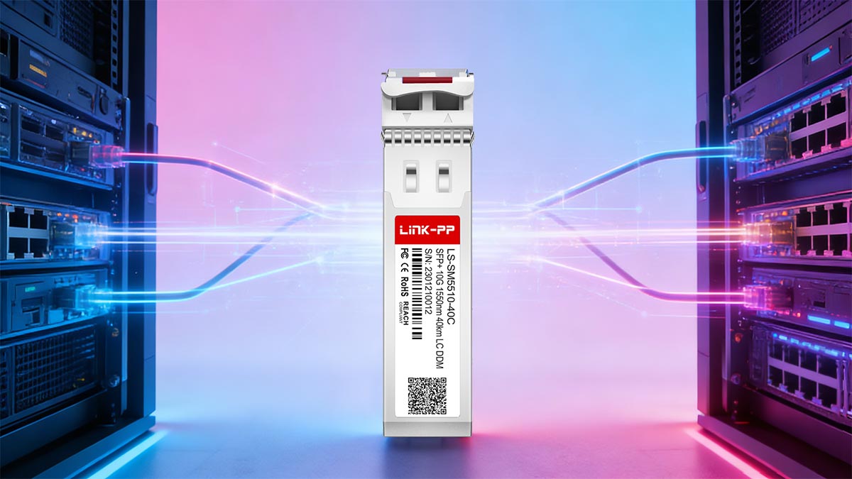
In optical network architecture, a SFP de larga distancia transceiver functions as the physical-layer interface that enables Layer 2 and Layer 3 traffic to traverse extended fiber spans without regeneration. It bridges switches, routers, and transport equipment across metro, inter-campus, and carrier backbone environments where distances exceed the limits of short-reach optics.
Within hierarchical network design, long distance transceivers typically serve three key roles:
Inter-building and campus aggregation
Connecting core switches across geographically separated facilities (10–40 km range).Metro and regional backbone links
Supporting aggregation and distribution layers in service provider or large enterprise networks (40–80 km range).Long-haul and DWDM transport integration
Operating within wavelength-division multiplexing systems where multiple channels share a single fiber pair (80 km and beyond).
Technically, the Transceptor SFP defines the optical budget envelope of a link—its transmit power, receiver sensitivity, and wavelength determine whether the physical span can sustain error-free transmission at a specified bit rate. In this sense, it is not merely a pluggable module but a performance boundary that governs reach, scalability, and interoperability within the broader optical system.
Because modern Ethernet standards formalize reach categories (LR, ER, ZR), long distance transceivers ensure multi-vendor compatibility when deployed according to standardized power and wavelength specifications. Their role is therefore both functional (signal transmission) και architectural (network extension and scalability) within optical infrastructure.
⭐️ Long Distance Transceiver Transmission Windows: 1310nm vs. 1550nm
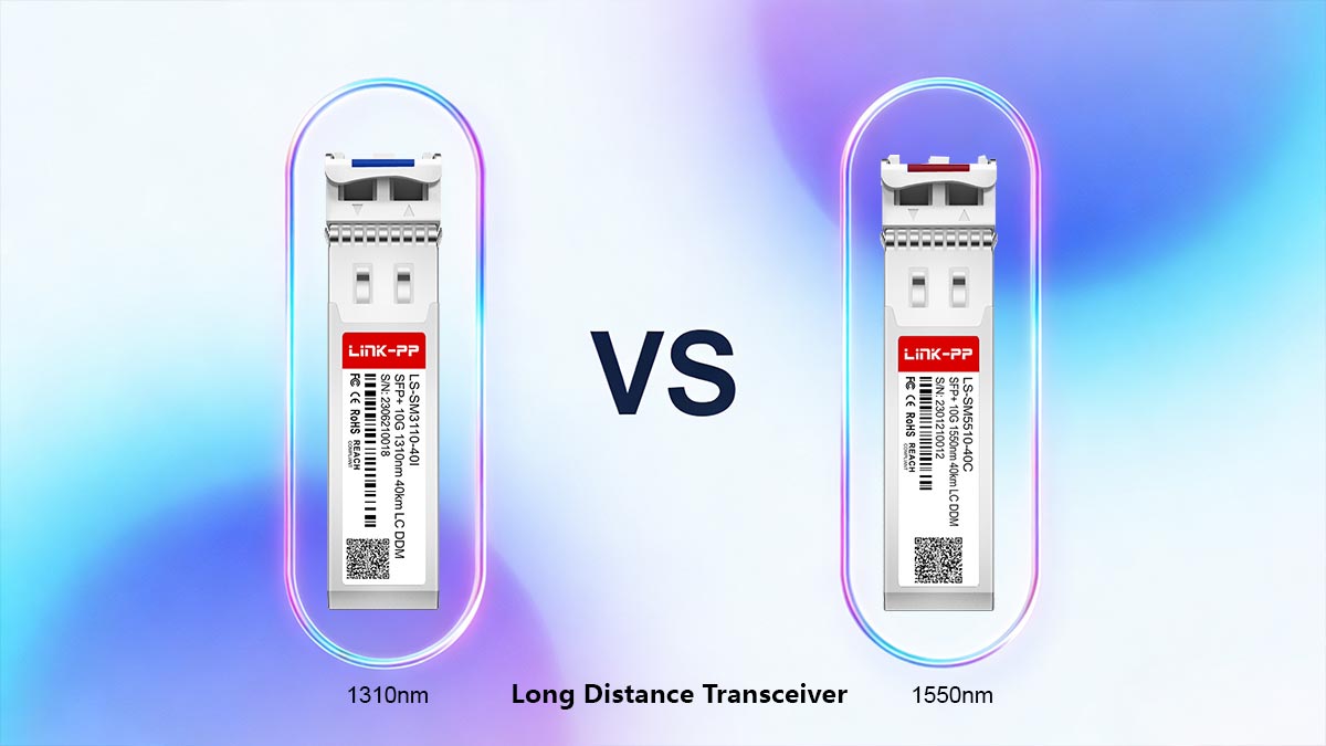
Elegir entre 1310 nm και 1550 nm is a fundamental decision in long distance transceiver design. While both operate over single-mode fiber (SMF), their attenuation characteristics, dispersion behavior, and amplification compatibility differ significantly.
▶ Attenuation Comparison
Fiber attenuation directly determines achievable reach and required optical budget.
For standard single-mode fiber (ITU-T G.652.D), typical values are:
1310 nm: ~0.32–0.35 dB/km
1550 nm: ~0,20–0,25 dB/km
Because attenuation at 1550 nm is approximately 30–40% lower than at 1310 nm, total span loss increases more slowly with distance. For example:
40 km at 1310 nm → ~13–14 dB fiber loss
40 km at 1550 nm → ~8–10 dB fiber loss
This difference becomes increasingly significant beyond 40 km, where optical margin becomes tighter.
▶ Chromatic Dispersion Impact
Chromatic dispersion behaves differently in each window:
Στην 1310 nm, dispersion is near zero (~0 ps/nm·km for G.652 fiber).
Στην 1550 nm, dispersion is higher (typically ~16–18 ps/nm·km).
Lower dispersion at 1310 nm simplifies 10G transmission up to 10–20 km without compensation. However, as distance increases, attenuation—not dispersion—becomes the dominant limitation.
At higher data rates (25G, 40G, 100G), dispersion at 1550 nm must be carefully managed, sometimes requiring dispersion compensation modules (DCM) or coherent detection techniques in advanced systems.
▶ EDFA Compatibility
A critical advantage of 1550 nm transmission is compatibility with erbium-doped fiber amplifiers (EDFAs).
EDFAs operate efficiently in the C-band (approximately 1530–1565 nm), which falls within the 1550 nm transmission window. This allows:
Optical signal amplification without electrical regeneration
Extended reach beyond 80 km
Support for DWDM channel grids
1310 nm systems do not benefit from practical EDFA amplification, which limits their scalability for very long spans.
▶ Why 1550nm Dominates Beyond 40km
Although 1310 nm performs well for 10 km and many 40 km links, 1550 nm becomes the preferred choice beyond 40 km due to:
Lower attenuation per kilometer
Compatibility with optical amplification
Soporte para la multiplexación por división de longitud de onda densa (DWDM)
Higher achievable optical power budgets
In practical deployments, 40 km links may use either wavelength depending on design constraints, but 80 km and longer spans are predominantly 1550 nm-based, often using ER or ZR class optics.
In summary, 1310 nm offers simplicity and low dispersion for moderate distances, while 1550 nm provides superior attenuation performance and scalability for long-haul and amplified networks.
⭐️ Reach Classes Explained: 10km, 40km, 80km, 120km
Long distance transceivers are commonly categorized by standardized reach classes that define maximum supported span under specified optical budgets. These categories—LR, ER, and ZR—correspond to increasing transmit power, receiver sensitivity, and dispersion tolerance.
While exact specifications vary by data rate (1G, 10G, 25G, 100G), the following classifications reflect typical 10G Ethernet implementations aligned with IEEE 802.3ae and industry practice.
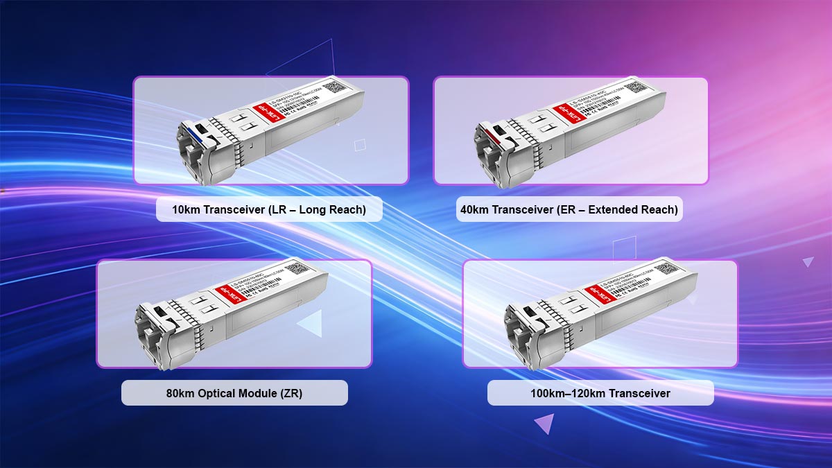
1. 10km Transceiver (LR – Long Reach)
Typical designation: 10GBASE-LR
Longitud de onda: 1310 nm
Tipo de fibra: Fibra monomodo (SMF)
Typical optical budget: ~6–8 dB
Typical power range (example values):
Tx output: ~ –8.2 dBm to +0.5 dBm
Rx sensitivity: ~ –14.4 dBm
10km transceivers operate near the zero-dispersion window of 1310 nm, simplifying transmission. Amplification is not required. These modules are widely used for campus and intra-metro connections.
2. 40km Transceiver (ER – Extended Reach)
Typical designation: 10GBASE-ER
Longitud de onda: 1550 nm
Tipo de fibra: SMF
Typical optical budget: ~14–17 dB
Typical power range (example values):
Tx output: ~ –1 dBm to +4 dBm
Rx sensitivity: ~ –15.8 dBm
At 40 km, attenuation becomes the primary limiting factor. The lower fiber loss at 1550 nm makes ER optics more practical than 1310 nm alternatives for full-distance spans. Amplification is generally not required for standard 40 km deployments, provided the link budget is within specification.
3. 80km Optical Module (ZR)
Typical designation: 10G ZR (often vendor-specific)
Longitud de onda: 1550 nm
Tipo de fibra: SMF
Typical optical budget: ~23–25 dB
Typical power range (example values):
Tx output: ~ 0 dBm to +5 dBm
Rx sensitivity: ~ –24 dBm
An 80km optical module typically operates in the 1550 nm window due to lower attenuation (~0.20–0.25 dB/km). Chromatic dispersion at this distance becomes significant and must be considered in design calculations.
Amplification may not be required for clean fiber spans, but margin becomes tighter. In carrier networks, EDFAs are often introduced for improved stability.
4. 100km–120km Transceiver
Typical designation: Transceptor de 100 km or enhanced ZR
Longitud de onda: 1550 nm (often DWDM channel)
Tipo de fibra: SMF
Typical optical budget: ≥25 dB
At 100 km and beyond, fiber attenuation alone can approach 20–25 dB, excluding connector and splice losses. In practical deployments:
Optical amplification (EDFA) is commonly required.
DWDM integration is typical.
Dispersion compensation may be necessary depending on data rate.
These modules are frequently deployed in metro-core and regional backbone environments.
5. LR vs ER vs ZR: Engineering Summary
Reach Class | Distancia | Longitud de onda típica | Presupuesto óptico | Amplification Needed |
|---|---|---|---|---|
LR | 10 km | 1310 nm | ~6–8 dB | No |
ER | 40 km | 1550 nm | ~14–17 dB | No (standard span) |
ZR | 80 km | 1550 nm | ~23–25 dB | Μερικές φορές |
Enhanced ZR | 100–120 km | 1550 nm / DWDM | ≥25 dB | Typically yes |
6. When Amplification Is Required
Optical amplification becomes necessary when:
Total link loss exceeds the module’s available optical budget
The span exceeds ~80 km in standard G.652 fiber
Multiple DWDM channels require equalized power levels
Additional margin is required for aging and environmental variation
In summary, the difference between a 10km transceiver and a 100km transceiver is not simply higher transmit power—it is the result of engineered optical budget scaling, wavelength selection, and dispersion management.
⭐️ Long Distance SFP vs. SFP+ vs. QSFP
When designing long-haul optical links, understanding the differences between SFP, SFP+, και Transceptores QSFP is critical for proper deployment. These modules vary in form factor, speed capability, power consumption, and thermal characteristics, all of which impact network planning for long distance applications.
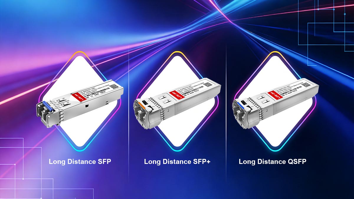
Form Factor Differences
SFP (conector modular de pequeño formato)
Normalmente soporta 1G–4G speeds, suitable for basic long distance links up to 10–40 km (LR/ER class).
Compact, single-lane module.
SFP+
Enhanced SFP variant supporting Ethernet 10G and some 16G/25G applications.
Same physical footprint as SFP but improved electrical interface and higher speed.
QSFP (Quad Small Form-factor Pluggable)
Admite 4 canales per module, commonly 40G ή 100G (with QSFP28/100G).
Larger module, higher density, suitable for data center spine-leaf or carrier aggregation.
Consumo de energía
Higher speed modules consume more power:
Módulo | Consumo típico de energía |
|---|---|
SFP | 0.5–1.0 W |
SFP+ | 1,0–1,5 W |
QSFP | 2.5–4.0 W |
Higher power may require attention to switch thermal management, especially for long-distance links where reliability is critical.
Disipación térmica
Módulos SFP generate minimal heat due to lower speed and power.
Módulos SFP+ produce moderate heat and may require airflow management in densely populated chassis.
Módulos QSFP require active cooling or sufficient airflow to maintain safe operating temperatures in high-density racks.
Effective heat dissipation is crucial to maintain long-term optical performance and avoid premature transceiver failure.
Compatibilidad de velocidad
SFP: Up to 4–10G, depending on variant
SFP+: Up to 10–25G, backward-compatible with SFP for lower-speed ports
QSFP/QSFP28: 40–100G, often requires breakout cables or aggregation for lower-speed compatibility
For 10G long distance transceivers, SFP+ is typically the module of choice, balancing reach, power, and cost while maintaining compatibility with most 10G-capable network devices.
In summary, choosing between SFP, SFP+, and QSFP for long-distance links depends on required speed, reach, power/thermal constraints, and port density. Proper selection ensures reliable long-haul performance while optimizing network design and energy efficiency.
⭐️ Optical Link Budget Calculation for Long Distance
A critical step in designing long distance fiber links is performing an cálculo del presupuesto del enlace óptico, which ensures that the transceiver’s output power, fiber loss, and receiver sensitivity collectively provide sufficient margin for reliable operation.

Link Budget Formula
The general optical link budget can be expressed as:
Available Margin (dB) = Tx Output (dBm) − Total Link Loss (dB) − Rx Sensitivity (dBm)
Donde:
Tx Output = Transmitter output power
Sensibilidad de recepción = Receiver minimum sensitivity
Pérdida total del enlace = Fiber attenuation + Connector loss + Splice loss + Contingency margin
A recommended minimum system margin is ≥ 3 dB to account for aging, temperature variation, and unforeseen loss.
Fiber Attenuation Calculation
Fiber attenuation is wavelength-dependent. For standard SMF G.652.D:
1310 nm: ~0.35 dB/km
1550 nm: ~0.20 dB/km
Total fiber loss (dB) = Fiber attenuation × Distance (km)
Connector and splice losses should also be included:
Typical connector: 0.5 dB each
Typical splice: 0.1–0.2 dB each
Worked Example: 40 km Link
Designing a 10GBASE-ER transceiver link at 1550 nm:
Elemento | Παράμετρος |
|---|---|
Tx Output | +3 dBm |
Sensibilidad de recepción | –15.8 dBm |
Ίνα | 40 km SMF, 0.25 dB/km |
Conectores | 2 × 0.5 dB |
Splices | 4 × 0.2 dB |
Step 1 — Fiber loss
Fiber loss = 40 km × 0.25 dB/km = 10 dB
Step 2 — Connector loss
Connector loss = 2 × 0.5 dB = 1 dB
Step 3 — Splice loss
Splice loss = 4 × 0.2 dB = 0.8 dB
Step 4 — Total link loss
Total link loss = Fiber loss + Connector loss + Splice loss = 10 + 1 + 0.8 = 11.8 dB
Step 5 — Available margin
Available margin = Tx Output − Total Loss − Rx Sensitivity = 3 − 11.8 − (−15.8) = 7.0 dB
Step 6 — Margin check
The available margin of 7 dB exceeds the recommended 3 dB minimum, confirming that the 40 km link is feasible without amplification.
Notas
Include contingency margin (1–2 dB) for aging, temperature drift, or patch panel loss.
For distances exceeding 80 km, optical amplification (EDFA) may be required.
High-speed DWDM links should account for wavelength-dependent loss and crosstalk.
⭐️ Dispersion and Its Impact on Long-Haul Transmission
Dispersión cromática is a critical factor in long-haul fiber-optic transmission, particularly for links operating at 1550 nm over single-mode fiber (SMF). It occurs because different optical wavelengths travel at slightly different speeds within the fiber, causing pulse broadening that can degrade signal integrity and increase tasa de errores de bit tasa de errores de bits (BER).
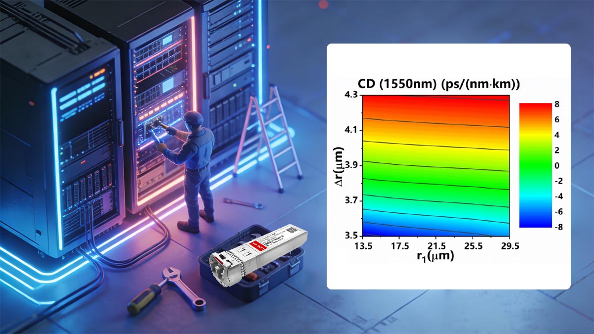
Chromatic Dispersion at 1550 nm
Standard SMF (G.652.D) exhibits typical chromatic dispersion of ~16–18 ps/nm·km at 1550 nm.
At 1310 nm, dispersion is near zero (~0 ps/nm·km), which is why 1310 nm optics are favored for short-reach links (<10 km).
For 1550 nm, accumulated dispersion grows linearly with distance. For example:
Ejemplo:
40 km × 17 ps/nm·km = 680 ps/nm total dispersion
While modest at 10G, this becomes significant for higher-speed links (25G, 100G) where symbol periods are shorter and pulse broadening can overlap adjacent bits.
Distance-Speed Relationship
The impact of dispersion scales with both distancia del enlace και velocidad de transferencia de datos:
Ταχύτητα | Symbol Period | Approx. Max Reach Without Compensation |
|---|---|---|
10G | 100 ps | 80 km (ER/ZR) |
25G | 40 ps | 40–50 km |
100G | 10 ps | 10–20 km |
As data rates increase, the same amount of accumulated dispersion reduces the maximum reach achievable without corrective measures.
Dispersion Compensation Modules (DCM)
When accumulated dispersion approaches the system’s tolerance, dispersion compensation modules (DCM) ή fiber Bragg gratings are introduced:
Actively or passively reduce pulse broadening
Restore timing alignment of optical pulses
Extend the effective reach of 1550 nm links without changing transceiver class
Advanced coherent detection technologies in 100G+ DWDM networks also allow electronic compensation, further mitigating chromatic dispersion.
When Dispersion Becomes the Limiting Factor
Dispersion is no longer negligible when:
Link distance exceeds 40–80 km at 25G+ rates
High spectral density DWDM channels are used
Receiver equalization and transceiver sensitivity cannot fully compensate pulse broadening
In these cases, optical engineers must calculate total accumulated dispersion and select appropriate DCM or coherent transceivers to maintain BER < 10⁻¹², ensuring error-free transmission over long-haul networks.
This section ensures network designers understand how dispersion interacts with wavelength, data rate, and distance, a critical consideration in selecting ER/ZR or DWDM transceivers for long-distance deployments.
⭐️ DWDM and Long Distance Transceivers
Sistemas de multiplexación por división de longitud de onda densa (DWDM) is a technology that allows multiple optical signals, each at a distinct wavelength, to share a single fiber. For transmisión de largo alcance, DWDM transceivers enable network operators to maximize fiber capacity while maintaining signal integrity over distances exceeding 40–80 km.
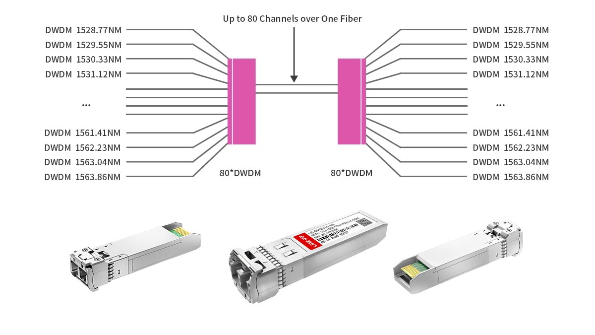
Espaciado entre canales
DWDM systems operate with precise channel spacing to prevent interference:
100 GHz spacing (~0.8 nm wavelength separation) — common in legacy and metro DWDM networks
50 GHz spacing (~0.4 nm wavelength separation) — used in high-capacity long-haul networks
Smaller spacing increases channel density but requires higher wavelength stability and tighter transceiver tolerances.
Wavelength Grid Concept
SFP DWDM transceivers adhere to the ITU-T standardized wavelength grid (C-band, ~1530–1565 nm):
Each channel is assigned a fixed wavelength according to the grid
Ensures multi-vendor interoperability
Allows simultaneous transport of dozens of channels on a single fiber without crosstalk
This concept enables operators to scale capacity without laying additional fiber, which is critical for metro, regional, and long-haul networks.
Tunable Optics
Advanced DWDM transceivers can feature tunable lasers, allowing the same hardware to operate on multiple DWDM channels:
Reduces inventory and simplifies network provisioning
Enables dynamic channel reassignment in response to traffic demand
Supports automated wavelength routing in reconfigurable optical add-drop multiplexers (ROADMs)
Tunable optics are increasingly common in high-capacity, long-haul deployments, particularly in networks supporting 100G, 400G, or beyond.
When DWDM Is Required
DWDM becomes necessary when:
Fiber capacity must be maximized without installing new fiber pairs
Link distances exceed standard ER/ZR spans, and amplification is used
Multiple services or clients share the same physical fiber infrastructure
Network operators need scalable upgrade paths for future high-speed transceivers
By combining long distance transceivers with DWDM systems, network designers achieve both extended reach and high spectral efficiency, making DWDM the preferred solution for modern long-haul optical networks.
⭐️ Common Long Distance Transceivers Deployment Mistakes
Η χρήση long range SFP transceivers requires careful attention to optical budget, wavelength selection, and equipment interoperability. Missteps can cause link instability, increased bit error rate, or even equipment errors. The most common mistakes include:

1. Overpowered Receiver (Rx)
Excessive optical power at the receiver can saturate the photodiode, causing:
Distorsión de la señal
Aumento de la tasa de errores de bit (BER)
Potential link instability
Ensure that the received power remains within the transceiver’s specified Rx range.
2. Under-Budget Margin
Failing to account for the full optical budget—fiber loss, connectors, splices, and contingency—can lead to:
Marginal links that degrade with fiber aging or temperature changes
Unexpected service interruptions
Μειωμένη μακροπρόθεσμη αξιοπιστία
A recommended minimum margin of 3–5 dB should always be maintained.
3. Using 1310nm Beyond Realistic Reach
1310 nm transceivers are suitable for ≤10 km (LR class) and sometimes up to 40 km in exceptional cases. Using them for longer spans introduces:
Υπερβολική εξασθένηση
Reduced link margin
Potential incompatibility with EDFA amplification (which operates at 1550 nm)
Always select the wavelength appropriate for the target span.
4. Ignoring Fiber Aging
Over time, fiber experiences:
Increased attenuation due to microbends, splices, and connector degradation
Environmental effects, such as temperature cycling
Neglecting fiber aging can reduce effective margin and shorten link lifespan. Include contingency for aging when calculating link budgets.
5. Firmware Compatibility Issues
Vendor firmware or transceiver coding mismatches can cause:
Err-disabled ports
Module recognition failures
DOM data inconsistencies
Always verify that transceiver firmware and host device firmware are compatible and follow vendor specifications.
By avoiding these common mistakes, network engineers can ensure stable, long-term operation of long distance transceiver links and maintain optimal performance across metro, regional, and long-haul networks.
⭐️ Validation Long Haul Transceiver Checklist Before Deployment
Before deploying long distance transceivers, performing a structured validation checklist ensures reliable operation, prevents link failures, and maximizes system lifespan. This checklist combines optical engineering best practices with equipment verification.
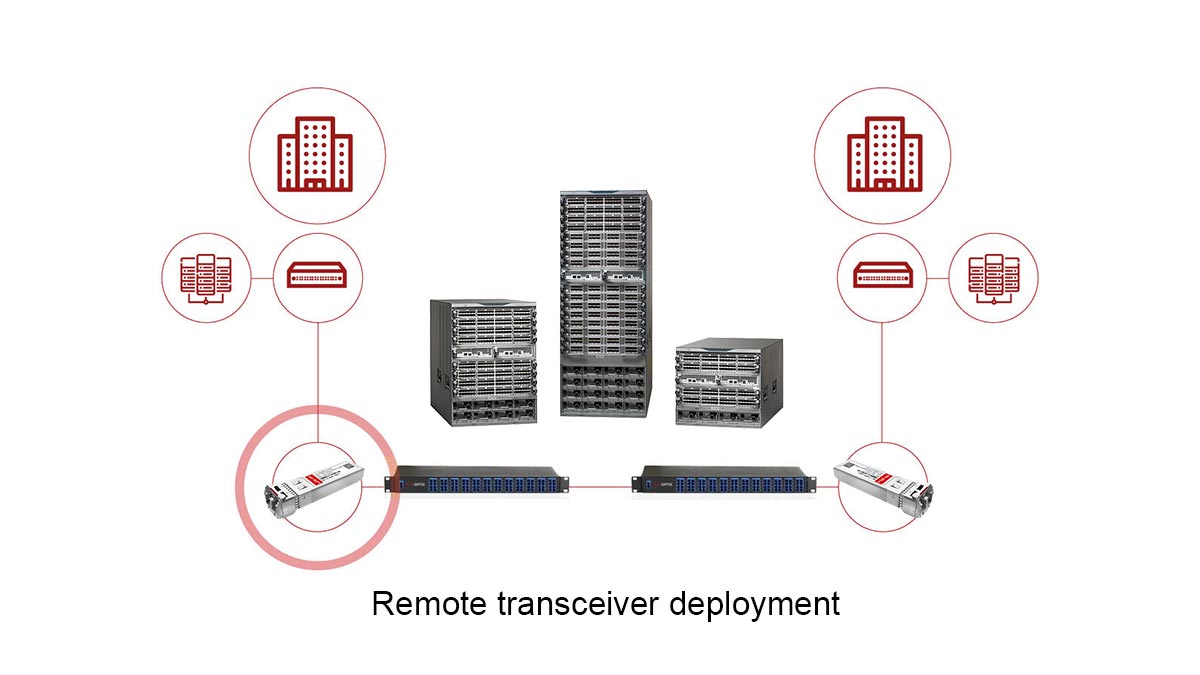
✔ Confirm Fiber Type (SMF Only)
Long distance transceivers are designed for ομομορφική φιλμ φόρμα (SMF). Using multimode fiber (MMF) can result in:
Υπερβολική εξασθένηση
Dispersión modal
Fallo de enlace
Always verify the fiber specification and connector type before module insertion.
✔ Calculate Total Link Loss
Perform a complete optical link budget calculation including:
Atenuación de la fibra. (dB/km × distance)
Connector losses (typically 0.5 dB each)
Splice losses (0.1–0.2 dB each)
Contingency margin (≥3 dB)
de interoperabilidad multiplataforma Tx power − total loss − Rx sensitivity ≥ recommended margin for reliable operation.
✔ Verify Rx Sensitivity
Check that the receiver’s minimum sensitivity matches the expected power at the fiber end. Overpowered or underpowered signals can cause:
Photodiode saturation
Bit errors or link flap
✔ Check Dispersion Limits
For long-haul 1550 nm links, la dispersión cromática can become limiting:
Calculate total accumulated dispersion (ps/nm)
Ensure it does not exceed transceiver tolerance
Consider DCM or coherent detection if necessary
✔ Validate Firmware Compatibility
Vendor firmware mismatches can lead to:
Err-disabled ports
Module recognition failure
Inconsistent Διαγνωστική Ψηφιακή Παρακολούθηση readings
Always verify transceiver firmware aligns with the host device and network management system.
✔ Confirm Wavelength Grid (DWDM)
Para DWDM deployments, confirm:
The transceiver operates on the correct ITU-T wavelength channel
Tunable optics are properly assigned
Channel spacing matches 50/100 GHz DWDM grid
Incorrect channel assignment can cause crosstalk and network degradation.
Following this checklist ensures that long distance transceivers are deployed with proper optical margin, wavelength alignment, and firmware support, minimizing troubleshooting and improving long-term network reliability.
⭐️ Long Range SFP Transceiver FAQs
Q1: How far can a long distance transceiver transmit?
A: Typical long distance transceivers reach 10 km (LR), 40 km (ER), 80 km (ZR), and 100+ km (enhanced ZR) depending on wavelength, fiber type, and optical budget.
Q2: Is 1550 nm always required for 40 km?
A: Not strictly, but 1550 nm is preferred due to lower fiber attenuation and compatibility with extended reach and DWDM systems. 1310 nm is generally limited to ≤10 km.
Q3: Can I connect a 40 km module to a 10 km link?
A: Yes, physically it can connect, but received power may be excessive, potentially saturating the Rx and reducing margin. A power adjustment or attenuator may be required.
Q4: What happens if optical power is too high?
A: Overpowered receivers can experience signal distortion, increased BER, and link instability. Always operate within the transceiver’s specified Rx range.
Q5: Do long distance transceivers require amplification?
A: Only when the total link loss exceeds the module’s optical budget, typically for spans >80–100 km or dense DWDM deployments. EDFA or inline amplifiers are used as needed.
⭐️ Long-Haul Transceiver Deployment Summary
Long distance transceivers are essential for high-speed, long-haul optical networks, enabling reliable connectivity over 10 km, 40 km, 80 km, or more. Correct selection of wavelength, link budget, and dispersion management ensures error-free transmission and network stability. Following the validation checklist and avoiding common deployment mistakes reduces operational risk and improves ROI.
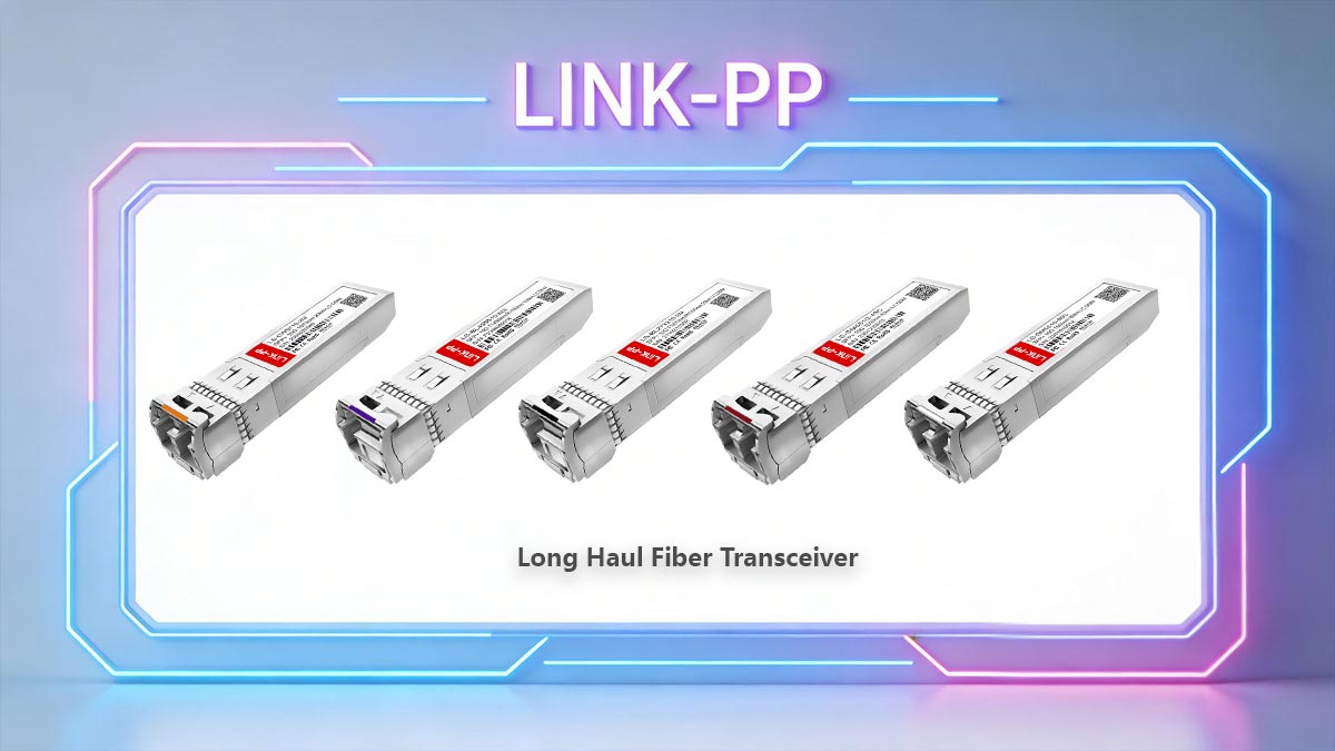
For verified, high-quality modules suitable for long-haul deployments, explore the Tienda oficial LINK-PP for SFP, SFP+, and DWDM transceivers designed to meet industry standards.
Normas y cumplimiento
Long distance optical modules adhere to recognized industry standards, ensuring interoperability, safety, and predictable performance:
IEEE 802.3ae / 802.3ba – Defines 10G/40G Ethernet optical interfaces and standardized reach classifications (LR, ER, ZR).
SFF-8472 – Specifies DOM (Digital Optical Monitoring) capabilities, enabling real-time monitoring of optical power, temperature, and voltage.
Cumplimiento de las normas de seguridad óptica – Ensures modules meet IEC/EN standards for eye safety and laser classification.
Adhering to these standards provides engineering confidence, reduces integration risk, and allows network operators to maintain high-performance, safe, and reliable long-haul optical links.