















🔄 Introduzione
Rumore in modo comune is a common challenge in Ethernet and other high-speed digital systems. It occurs when identical noise voltages or currents appear on both conductors of a pair relative to ground. Left unmitigated, it can lead to interferenza elettromagnetica (EMI), compliance failures, and degraded signal integrity. This article explains the concept, causes, measurement methods, and suppression techniques of common-mode noise — with a focus on Ethernet design and LINK-PP LAN transformers.
🔄 What Is Common-Mode Noise?
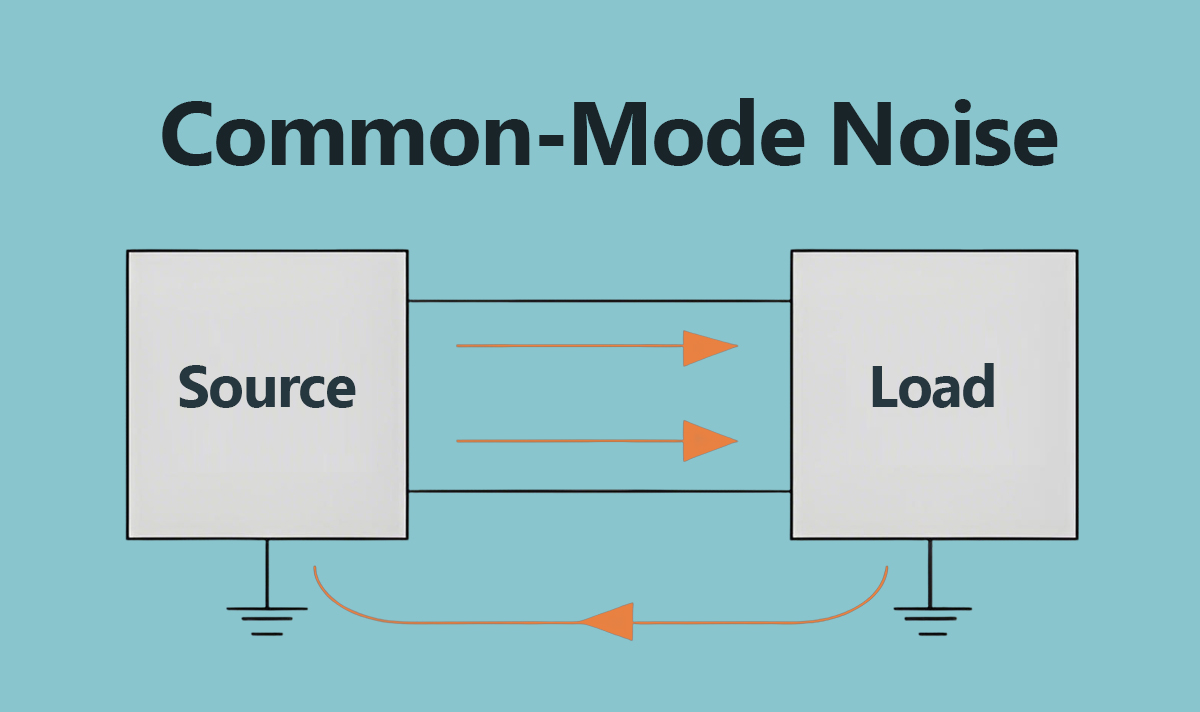
Common-mode noise refers to unwanted signals that appear in the same phase on two conductors relative to ground.
Formula:
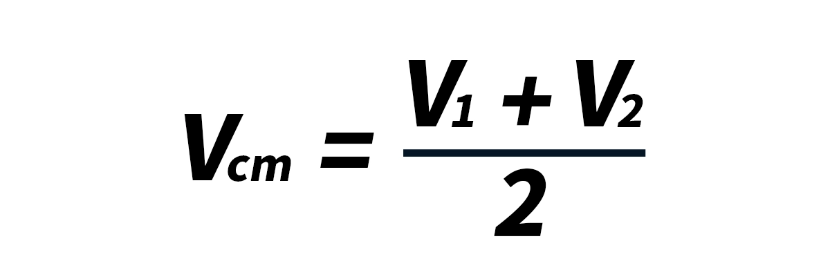
In contrast, the useful che quelle in modo differenziale. signal is:

While differential-mode signals carry data, common-mode noise represents interference that may radiate as EMI or couple into sensitive circuitry.
🔄 Differential Mode vs Common Mode
Aspetto | Differential Mode | Common Mode |
|---|---|---|
Signal | Opposite polarity on conductors | Same polarity on both conductors |
Scopo | Carries data | Unwanted interference |
Radiation | Relatively low | High, cables act as antennas |
Reference | Between lines | Relative to ground |
Mitigazione | Pair symmetry, impedance control | Induttori per modo comune, isolation |
🔄 Causes of Common-Mode Noise
External coupling: Switching circuits or nearby cables can induce equal disturbances on both lines.
Ground potential differences: Mismatched system grounds create common-mode offsets.
Mode conversion: Layout or driver imbalance converts differential signals into common mode.
Parasitic capacitance: Line-to-chassis coupling at high frequencies promotes current leakage.
🔄 Why Common-Mode Noise Matters in Ethernet
Compatibilità: Excessive common-mode emissions can cause systems to fail EMI/EMC tests.
per interfacce ottiche ed elettriche ad alta velocità: High common-mode levels reduce differential receiver rejection.
Interference risk: Noise can couple into nearby analog or control circuits.
Isolation stress: Particularly in PoE systems, common-mode current may strain isolation boundaries.
🔄 Measuring Common-Mode Noise
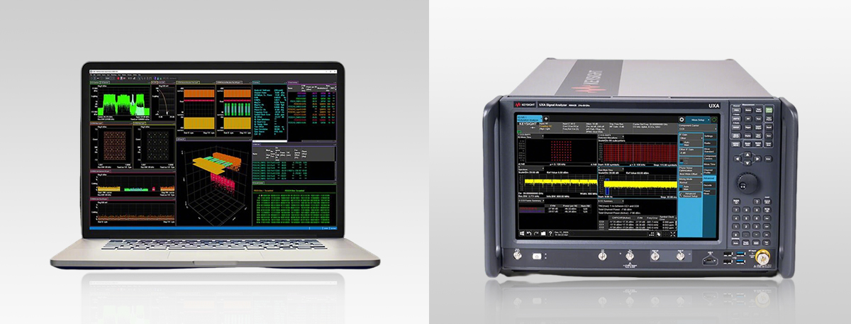
Clamp-on current probes + spectrum analyzers: Detect total common-mode current on cables.
LISN (Line Impedance Stabilization Network): Separates and measures conducted emissions.
Transfer impedance method: Converts probe readings into accurate current values.
🔄 Mitigation Strategies
Common-Mode Chokes
Common-Mode Chokes (CMCs) present high impedance to common-mode currents while allowing differential Ethernet signals to pass, making them the most effective filter.
Balanced PCB Design
Matched trace lengths, controlled impedance, and minimizing skew reduce mode conversion.
Schermatura
Utilizzando STP (shielded twisted pairs) with proper chassis grounding lowers capacitive coupling.
Isolamento
Trasformatori LAN provide galvanic separation and reduce common-mode transfer, though inter-winding capacitance must be considered in EMI budgets.
🔄 Conclusione
Rumore in modo comune is a major source of EMI in Ethernet and PoE designs. Effective suppression requires a combination of common-mode chokes, balanced PCB layouts, shielding, and isolation. By leveraging LINK-PP Trasformatori LAN and RJ45 magjacks with optimized EMI performance, engineers can achieve both regulatory compliance and robust Ethernet operation. Clear documentation of compatibility parameters — such as data rate, PoE current rating, insertion loss, and isolation — further simplifies design choices for customers.
🔄 Further Reading
Explore more technical resources from LINK-PP: