















La distorsion du signal désigne toute modification indésirable de la forme, de la synchronisation ou des caractéristiques d'origine d'un signal. Dans le domaine des réseaux et de la communication de données, la distorsion du signal signifie que les données envoyées par votre système ne correspondent pas exactement à celles qu'il reçoit, ce qui entraîne des erreurs, des pertes d'informations et des problèmes de performances.
1. Qu'est-ce que la distorsion du signal ?
La distorsion du signal Il s'agit de la modification indésirable de la forme, de la synchronisation, de l'amplitude ou de la phase d'origine d'un signal lors de son acheminement à travers des câbles, des connecteurs ou des appareils. Cela altère le message et augmente les taux d'erreur. .
En électronique numérique, même si les données sont représentées par des 1 et des 0, le signal proprement dit est analogique et sensible à des phénomènes tels que la réflexion, la perte et la diaphonie.
2. Types courants de distorsion du signal
Type | Description |
|---|---|
Distorsion d'amplitude | Une amplification ou une atténuation inégale des différentes composantes de fréquence, entraînant une altération de la forme d'onde. |
Distorsion de phase | Les différentes composantes de fréquence subissent des déphasages variables, ce qui entraîne une déformation de la forme d'onde. |
Distorsion non linéaire | Lorsqu'un signal traverse un système non linéaire, de nouvelles composantes de fréquence (par exemple, des harmoniques ou des intermodulations) sont générées, ce qui dégrade considérablement la qualité du signal. |
Distorsion transitoire | Les variations rapides du signal dépassent le temps de réponse du système, ce qui entraîne un étirement ou un retard de la forme d'onde. |
🔸 Atténuation et Perte d’insertion
L'amplitude du signal diminue en raison des pertes dues à la résistance et aux pertes diélectriques. Dans les connecteurs tels que les connecteurs RJ45 ou les modules à fibre optique, l'atténuation réduit la puissance et la clarté du signal.
🔸 Réflexion et désadaptation d'impédance
Lorsque l'impédance varie au niveau d'un connecteur ou d'une piste, une partie du signal est réfléchie, ce qui provoque une distorsion ou un “ oscillation ” du signal. Une terminaison adéquate est essentielle pour minimiser cette réflexion.
🔸 Couplage
Le couplage électromagnétique entre des lignes de signal proches les unes des autres (par exemple, dans les connecteurs RJ45 ou les paires différentielles des cartes électroniques) provoque des interférences qui altèrent la qualité du signal.
🔸 Dispersion (signaux optiques)
Face de fibre optique la dispersion chromatique, où les différentes longueurs d'onde se propagent à des vitesses différentes, et dispersion modale opto-électrique fibre multimode, ce qui entraîne un élargissement des impulsions et des interférences entre symboles (ISI).
🔸 Distorsion non linéaire
Dans les modules optiques ou les dispositifs magnétiques, une puissance élevée ou des matériaux imparfaits peuvent générer des harmoniques ou des phénomènes d'intermodulation, ce qui déforme encore davantage le signal.
3. Pourquoi la distorsion du signal est-elle importante ?
Plus élevé taux d'erreur binaire (BER): La distorsion augmente le nombre d'erreurs dans les liaisons numériques, en particulier à des débits de l'ordre du gigabit ou supérieurs.
Schémas « à yeux fermés » : Les diagrammes en œil permettent de visualiser la qualité du signal : si l“” œil » se ferme, la fiabilité de la transmission diminue.
erreurs et des retransmissions. Bande passante & Débit de données : Les signaux déformés véhiculent des informations moins fiables, ce qui limite les performances du système.
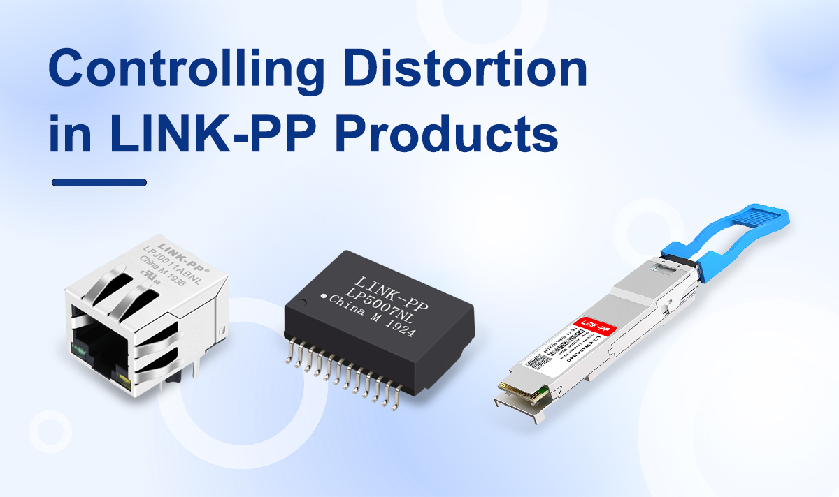
4. Maîtrise de la distorsion dans les produits LINK-PP
Les produits phares de LINK-PP — connecteurs RJ45, modules optiques (par exemple, modules SFP, 10 G et 25 G) et transformateurs Ethernet — sont conçus pour réduire au minimum la distorsion du signal grâce aux mesures suivantes :
★ — composants haute performance qui supportent les déploiements de réseaux DSL et FTTC.
Conçu avec une adaptation d'impédance précise et une terminaison de type Bob Smith afin de réduire les réflexions et les pertes d'insertion.
Faible Perte de retour and SUIVANT/FEXT Les spécifications relatives à la diaphonie garantissent la pureté des signaux différentiels.
Les consignes de conception des circuits imprimés (plan de masse, appariement des pistes) sont respectées afin de garantir l'intégrité du signal.
★ Modules optiques
Les émetteurs-récepteurs optiques comprennent Récupération d’horloge et de données (CDR) and FEC (correction d’erreurs directe) pour corriger la distorsion de la forme d'onde et la gigue de synchronisation.
Les spécifications du MODULE sont conformes aux normes IEEE (par exemple, sensibilité du récepteur en condition de contrainte, conformité au masque en œil) afin de résister aux effets de dispersion.
★ les transformateurs Ethernet
High Taux de réjection en mode commun (CMRR) pour atténuer le bruit et maintenir l'équilibre entre l'amplitude et la phase.
Sa conception magnétique résiste à la saturation et à l'intermodulation, préservant ainsi la fidélité du signal en cas de surtensions ou d'événements ESD.
5. Conseils pour réduire au minimum la distorsion du signal dans la pratique
Toujours maintenir l'adaptation d'impédance sur les connecteurs, les pistes des cartes électroniques et les câbles.
Réduire différences de longueur et tronçons dans l'acheminement des connecteurs RJ45.
Utilisez outils de simulation électromagnétique pour prévoir les réflexions et la diaphonie.
Pour les liaisons par fibre optique, respectez les bonnes pratiques : choisissez le type de fibre adapté, contrôlez la puissance d'émission, nettoyez régulièrement les connecteurs et testez les diagrammes en œil et les masques de sensibilité.
6. Distorsion, bruit et atténuation : comparaison rapide
Distorsion : Modification systématique de la forme du signal ; entraîne des erreurs de bits et des problèmes de compatibilité.
Bruit : Des interférences aléatoires s'ajoutent au signal, ce qui réduit la clarté globale.
L’atténuation : Réduit l'intensité du signal sans en modifier la forme ; une atténuation excessive peut compliquer la récupération.
Conclusion
La distorsion du signal est l'ennemi d'une transmission de données propre et fiable. Des connecteurs RJ45 aux modules optiques en passant par les transformateurs Ethernet, LIEN‑PP allie une conception et une ingénierie de précision pour réduire la distorsion, améliorant ainsi l'intégrité du signal dans l'ensemble des systèmes réseau.
Voir aussi
Pour en savoir plus sur les facteurs qui influent sur la distorsion du signal et l'intégrité globale du signal, consultez ces articles connexes disponibles dans le Centre de connaissances de LINK‑PP :
🔍 Perte d'insertion : impact sur le MagJack RJ45
Découvrez comment la perte d'insertion affecte la puissance du signal et quels sont les facteurs liés à la conception des connecteurs qui l'influencent.📉 Comprendre le taux d’erreur binaire (BER)
Une analyse approfondie de la manière dont la distorsion du signal entraîne un taux d'erreur binaire (BER) et comment celle-ci peut être minimisée dans des applications concrètes.🚀 Qu'est-ce que la bande passante de données ?
Découvrez comment la qualité du signal influe sur la bande passante et pourquoi il est important que les voies de transmission soient exemptes d'interférences.🔁 Perte de retour dans les connecteurs RJ45
Un facteur essentiel pour réduire au minimum la réflexion et préserver la fidélité du signal dans les réseaux à haut débit.🧭 Récupération synchronisée des données (CDR)
Découvrez comment la fonction CDR permet de corriger les signaux déformés et de rétablir la précision de synchronisation dans les émetteurs-récepteurs numériques.🛠️ Correction d’erreurs directe (CED)
Découvrez comment la technologie FEC permet de lutter contre la distorsion et les erreurs de transmission dans les systèmes à fibre optique à haut débit.